

Custom Tray Solution: From Design to Mass Production in Practice
▶️ Watch the teaser video
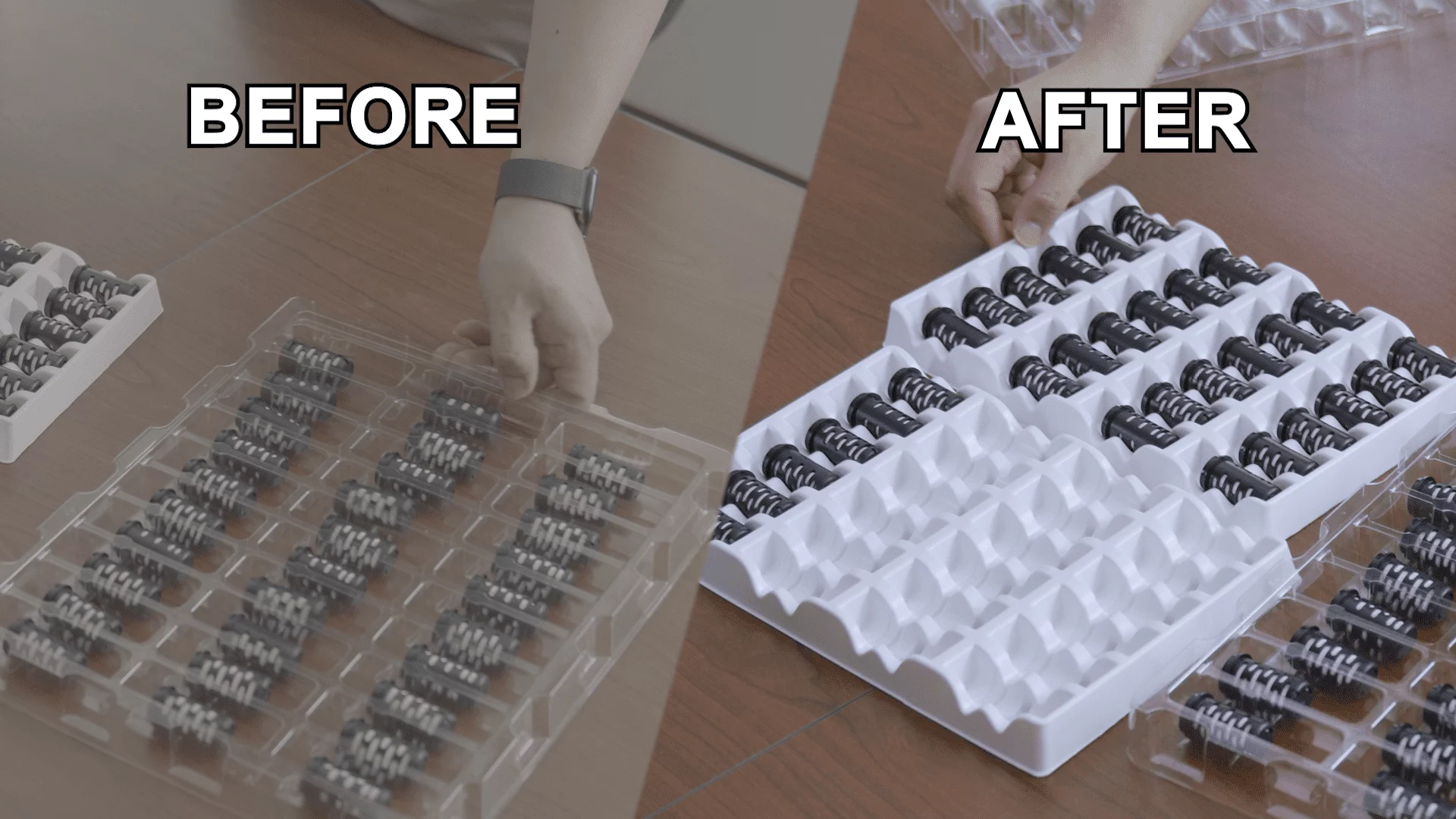
This article explores how to develop a custom tray solution for Mbranfiltra, a membrane filtration materials manufacturer, to ensure the protection and stability of water purifier components during manufacturing, transportation, and processing.
Faced with high minimum order quantities (MOQs) from traditional OEMs, we propose a self-made tray solution, documenting the complete process from requirements analysis, design iterations, and prototyping to mass production.
Through multiple rounds of design optimization and testing, challenges such as webbing , snap-fit issues, and cutting were successfully overcome, achieving low-cost, high-efficiency tray mass production.
1. Background and Requirements Analysis
In the water purifier manufacturing process, trays play a crucial role in protecting delicate filter elements, ensuring components remain undamaged during transport and processing.
However, standard trays on the market fail to meet Mbranfiltra’s specific needs, resulting in filter displacement and increased processing costs.
Additionally, the existing tray inventory in the factory is insufficient to meet traditional OEM MOQs, prompting the decision to develop a custom tray.
Limitations of Standard Trays
- Insufficient Protection: Filters tend to become dislodged during transport.
- Limited Capacity: Each tray holds only 30 water purifier components.
Objectives of the Custom Tray
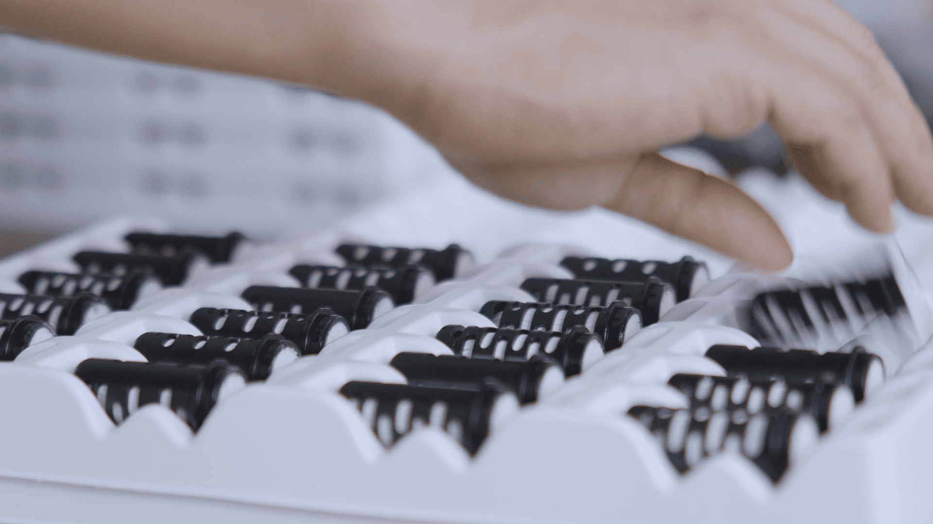
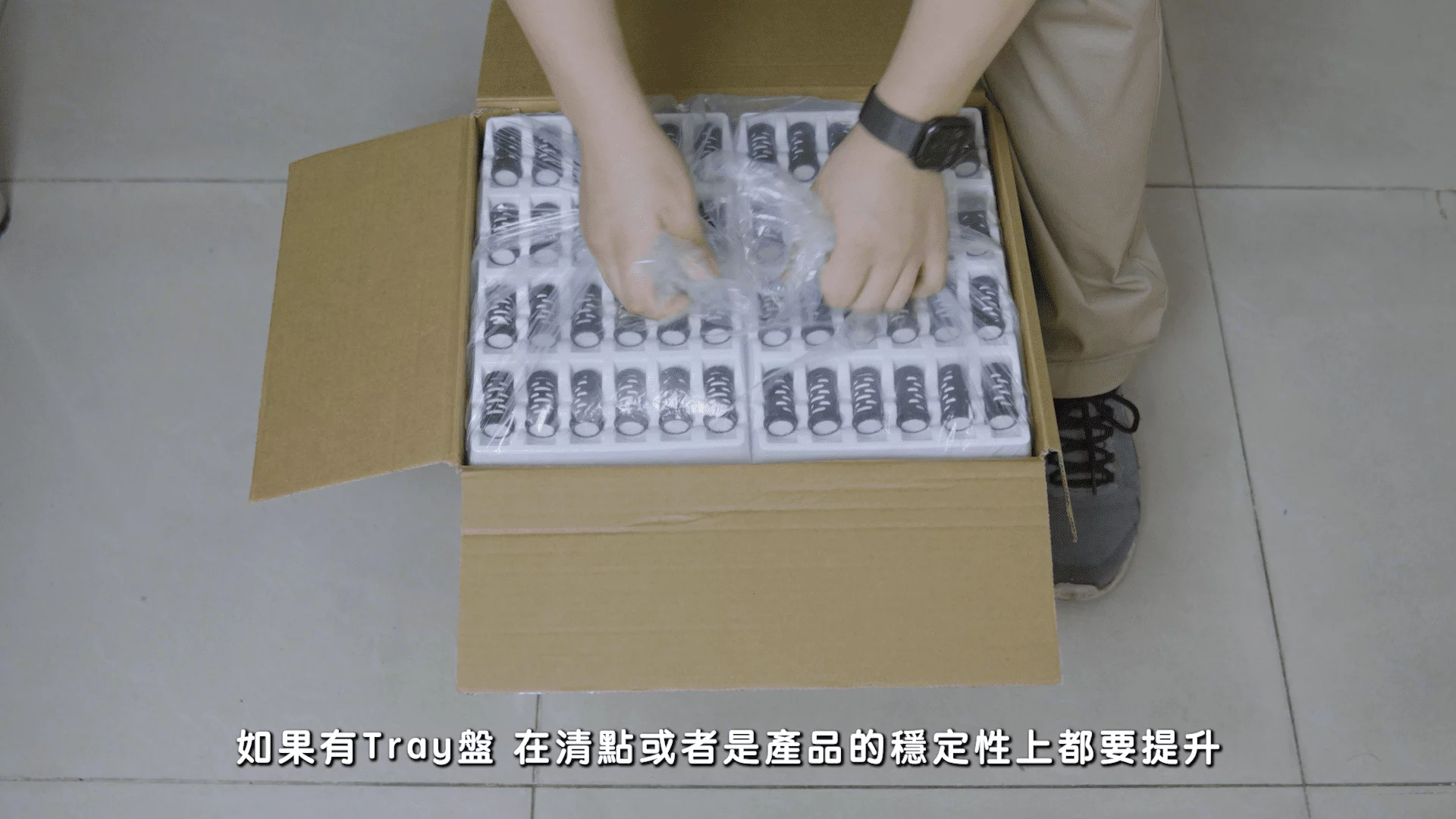
- Increased Capacity: Boost capacity by 50%, accommodating 45 components per tray.
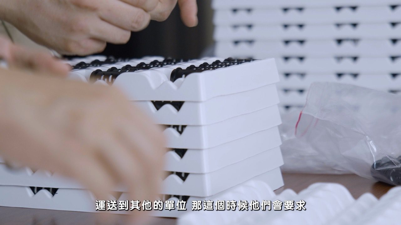
- Component Stability: Prevent movement and dislodgement during transport and stacking.
- Cost Reduction: Minimize additional costs from component damage.
2. Design and Prototyping
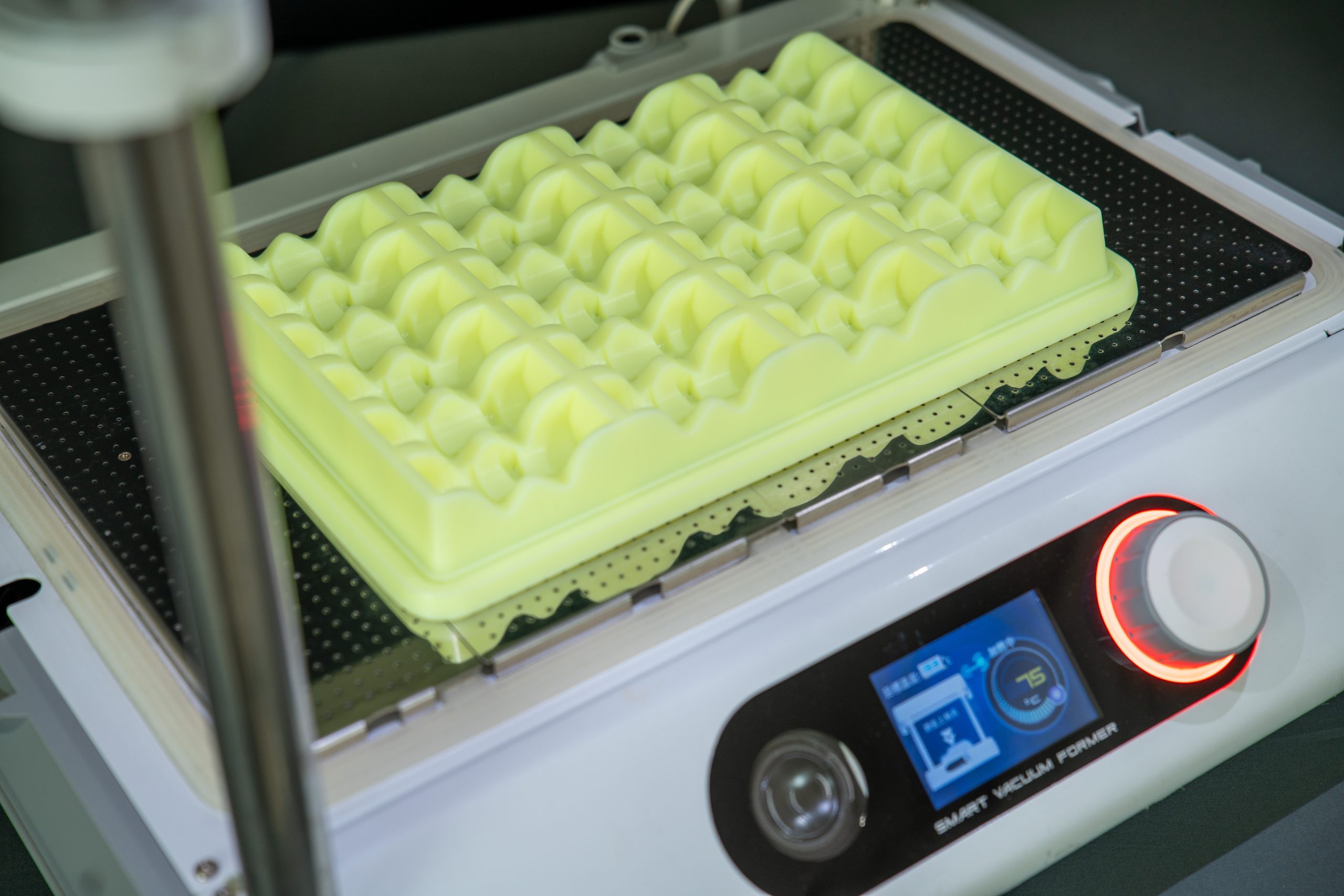
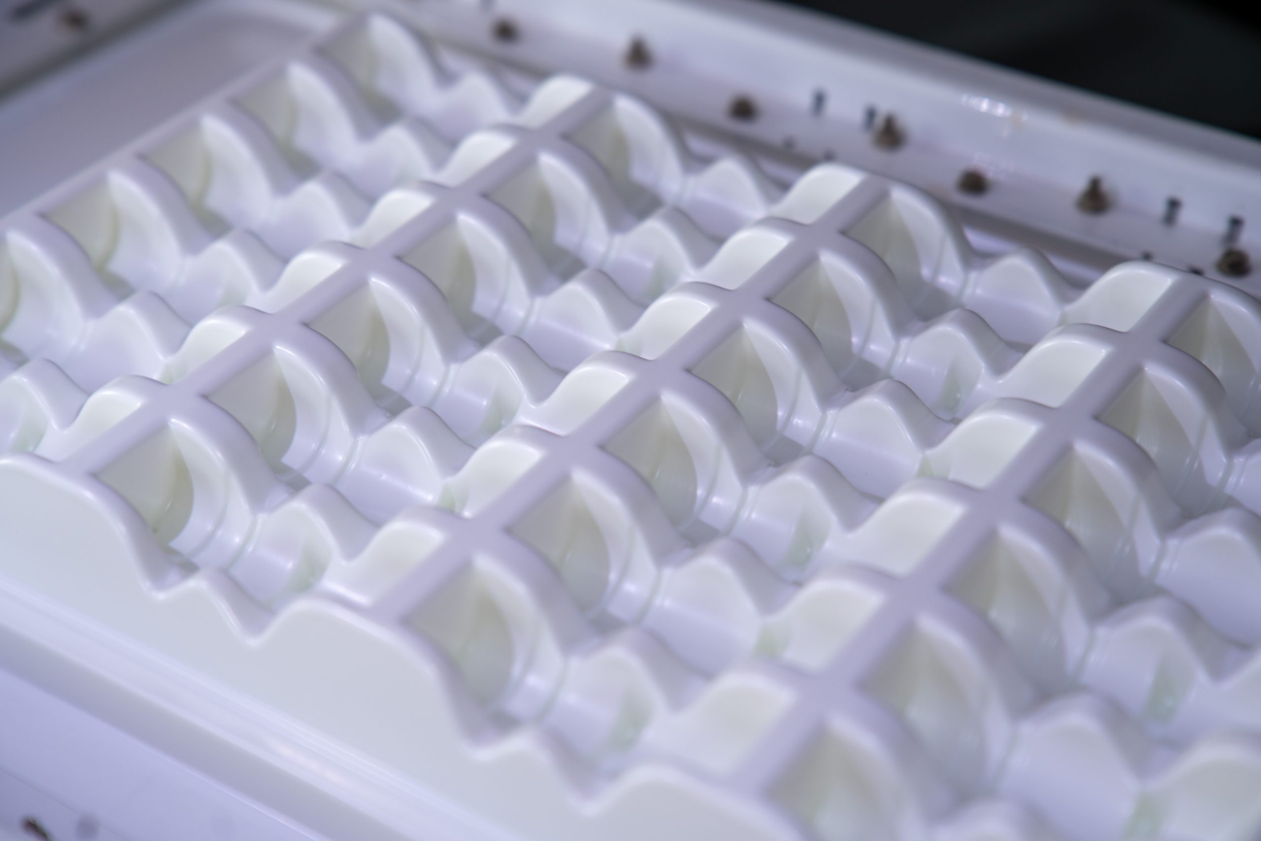
Version 1 Design: Enclosed Structure
The initial concept fully enclosed each water purifier component to provide maximum protection.
Testing showed this structure occupied too much space and caused webbing when arrayed,
reducing tray packing density.
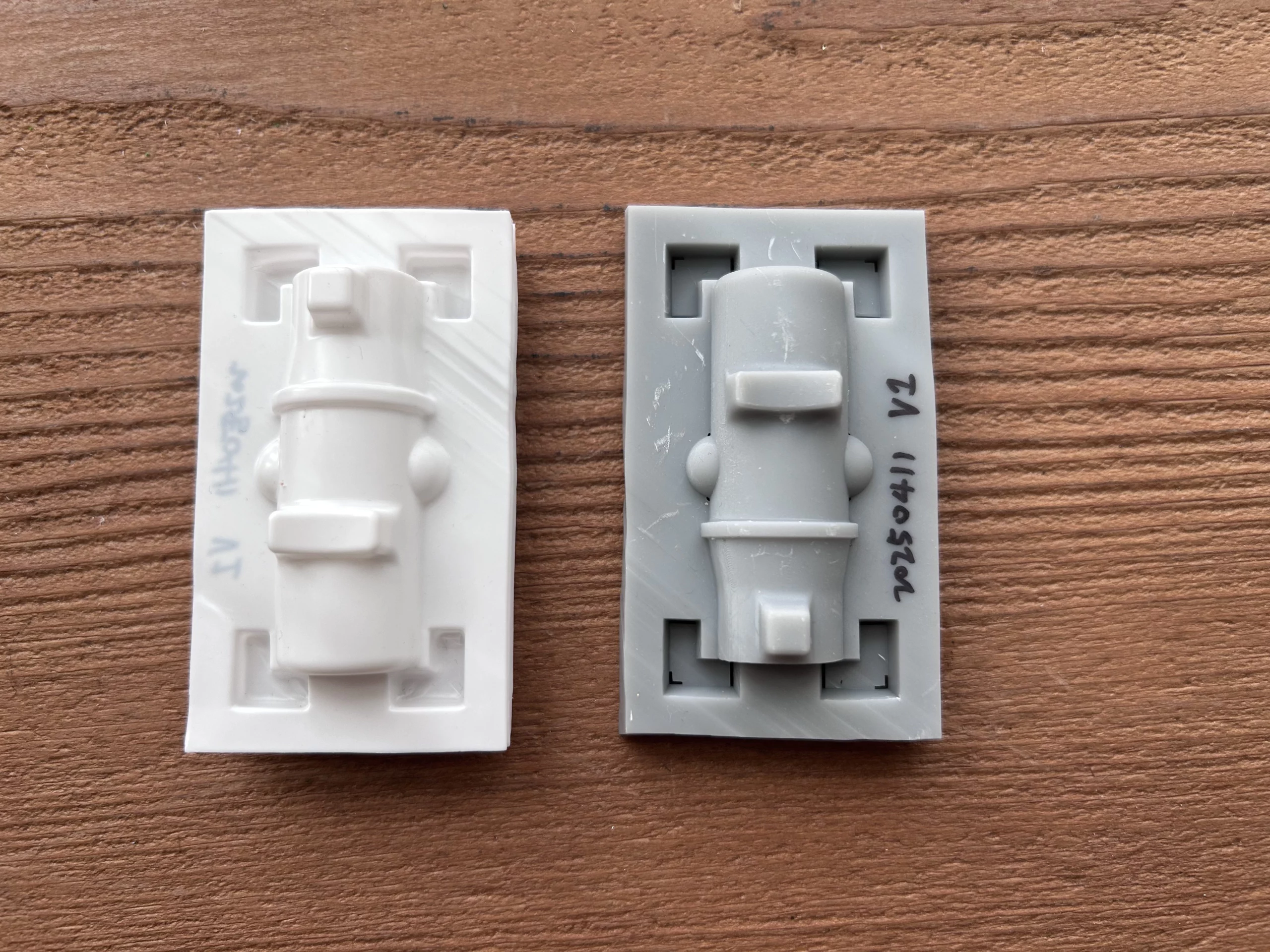
Version 2 Design: Simplified Structure & Stacking Challenges
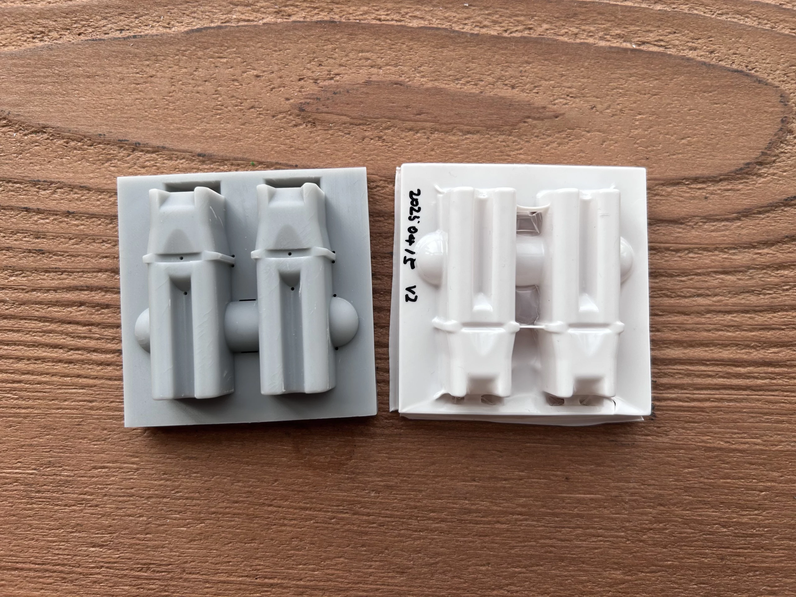
The second version simplified the tray structure but overlooked stacking stability.
The second layer of trays tended to slip, preventing secure stacking.
Version 3 Design: Snap-Fit Structure Adjustment
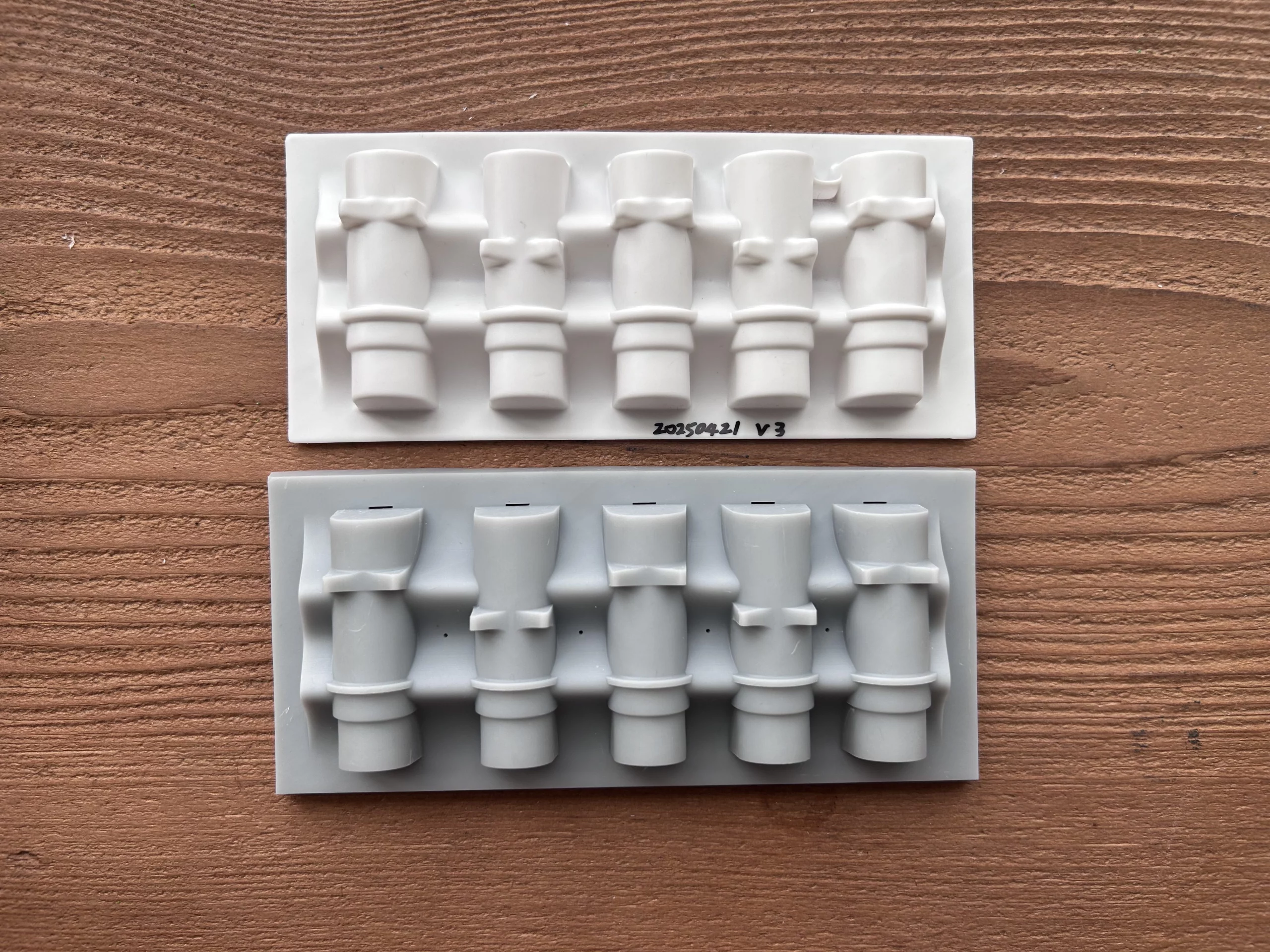
The third version readjusted the snap-fit features to improve stacking stability.
However, the added snaps consumed too much space, increasing tray height.
Version 4 Design: Negative Mold Challenges
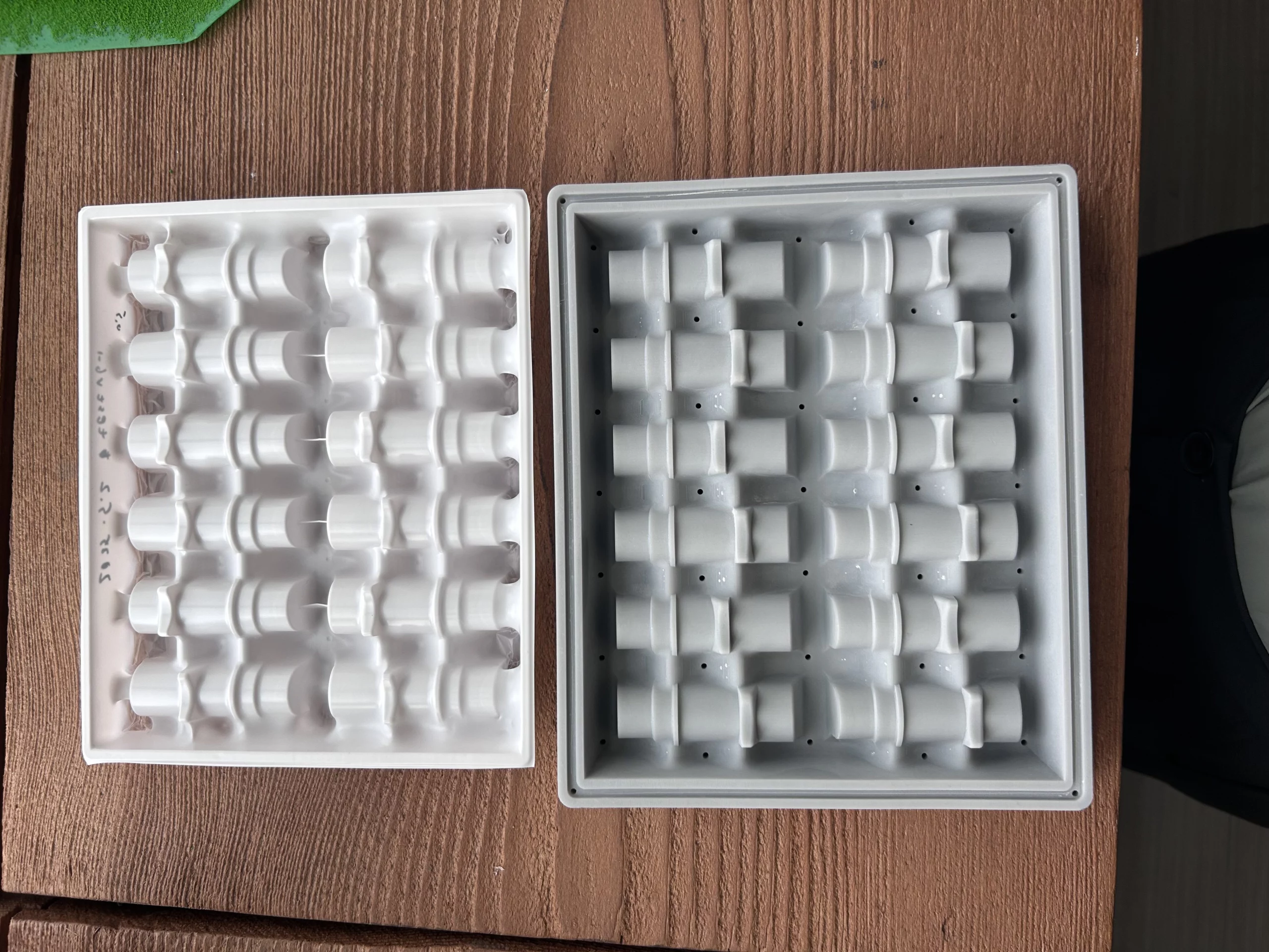
The fourth version used the component’s outer ring for snap-fit positioning with a negative mold design.
However, this caused severe webbing rendering the trays unusable.
Version 5 Design: Positive Mold Breakthrough
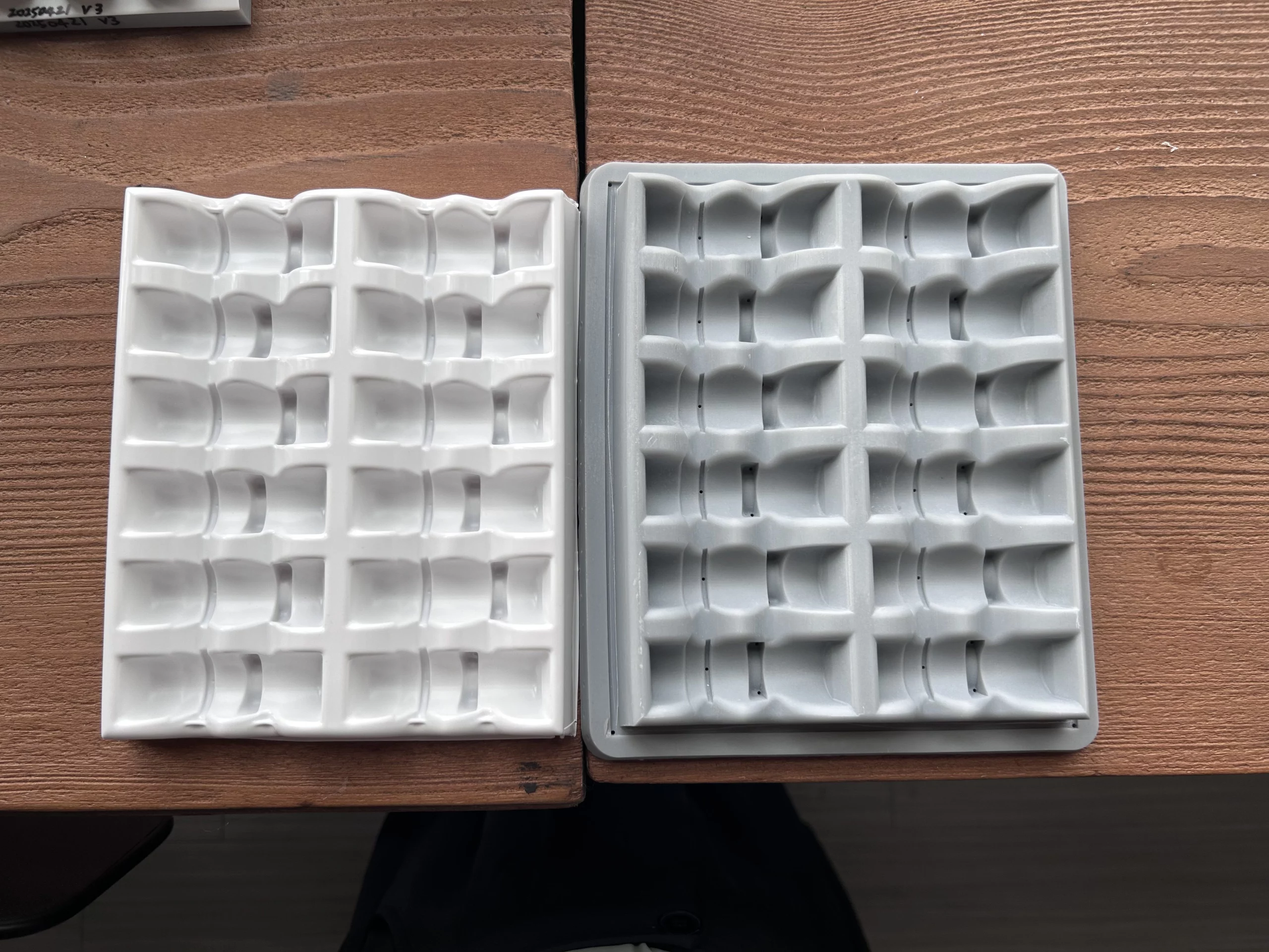
To overcome webbing, the fifth version switched to a positive mold.
This effectively eliminated webbing while retaining the negative mold’s snap-fit points.
Version 6 Design: Snap-Fit Fine-Tuning
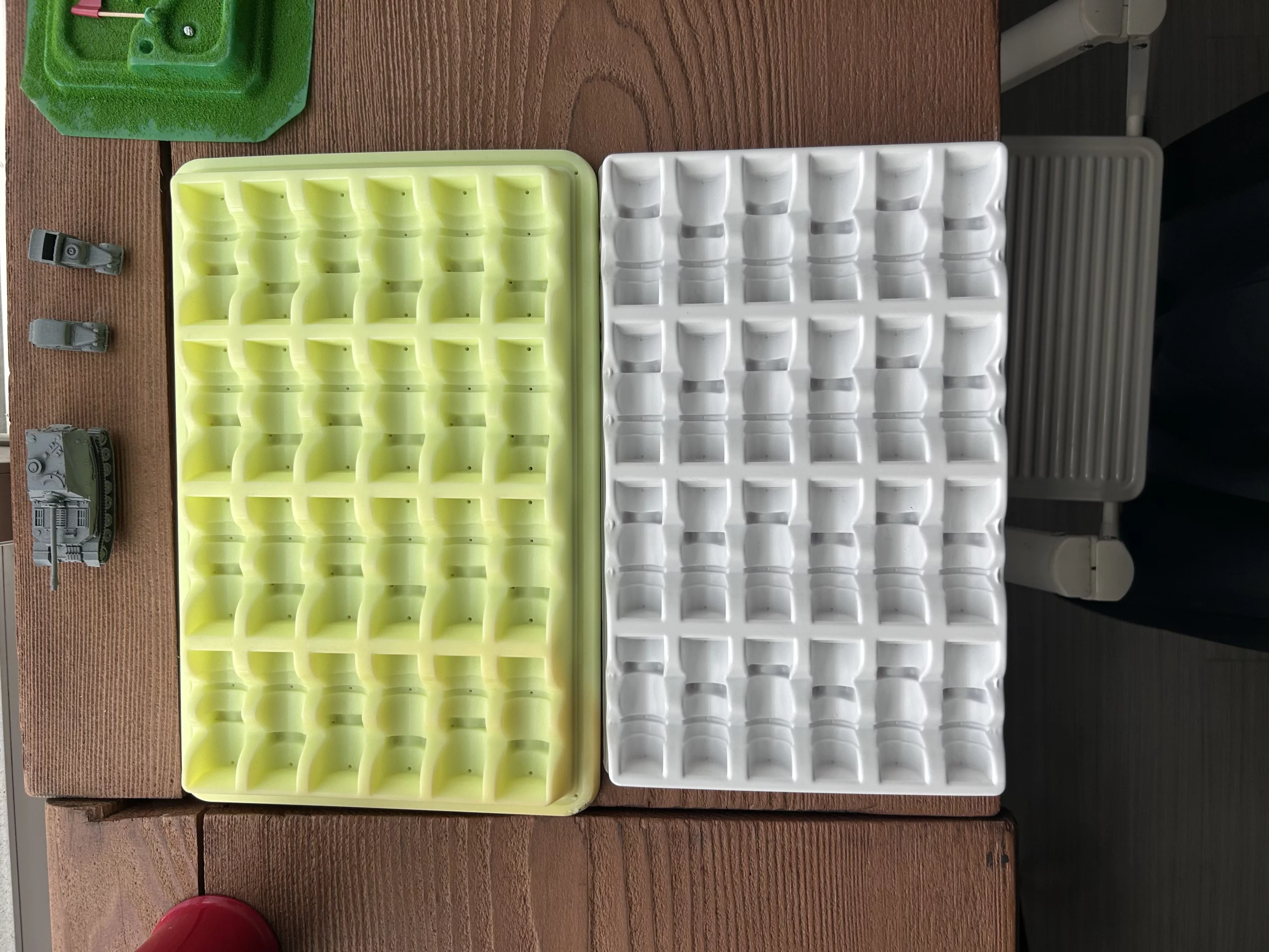
Due to dimensional differences between molds, the sixth version fine-tuned the snap-fit dimensions,
achieving secure retention and reliable stacking.
3. Mass Production Workflow & Cutting Jigs
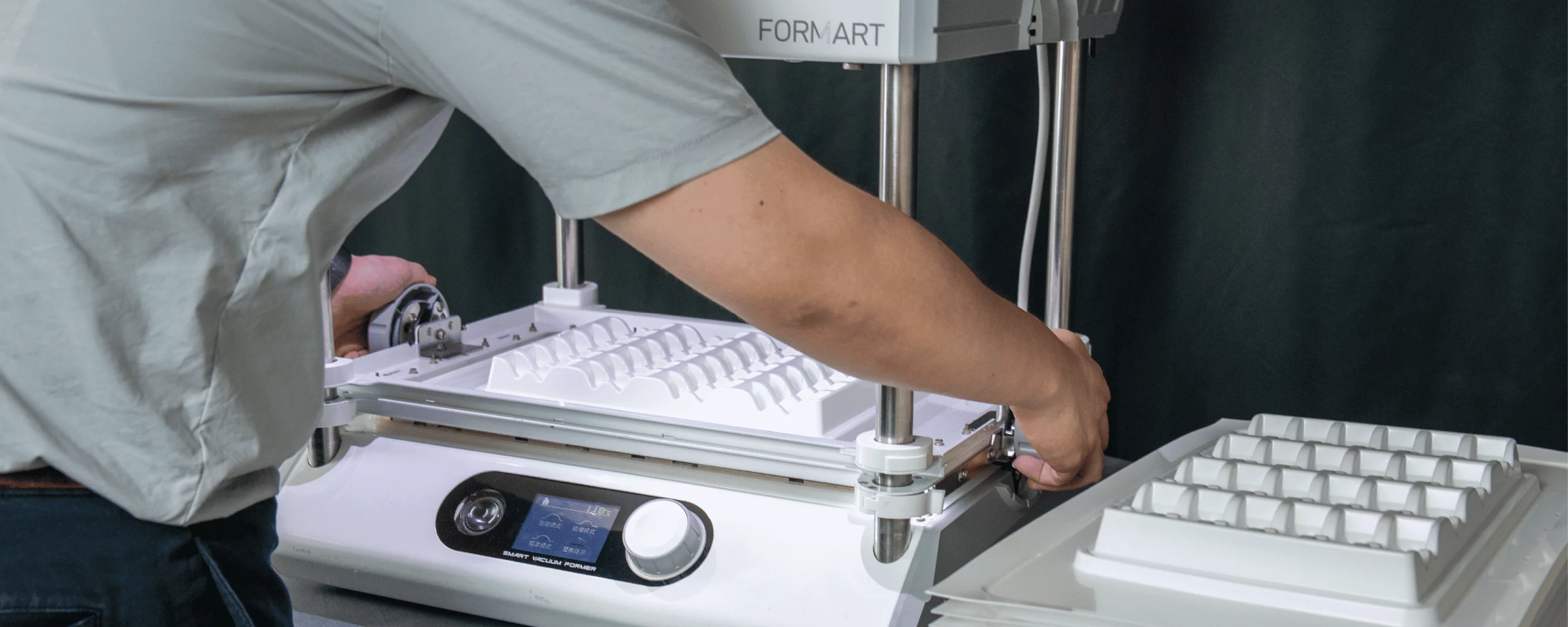
Cutting Jig Design
To enable mass production of custom trays, we designed a cutting jig for fast, precise trimming of formed shells.
Version 1 Cutting Jig: Limitations
The first jig left insufficient clearance and lacked clamping tightness, producing rough edges and inconsistent quality.
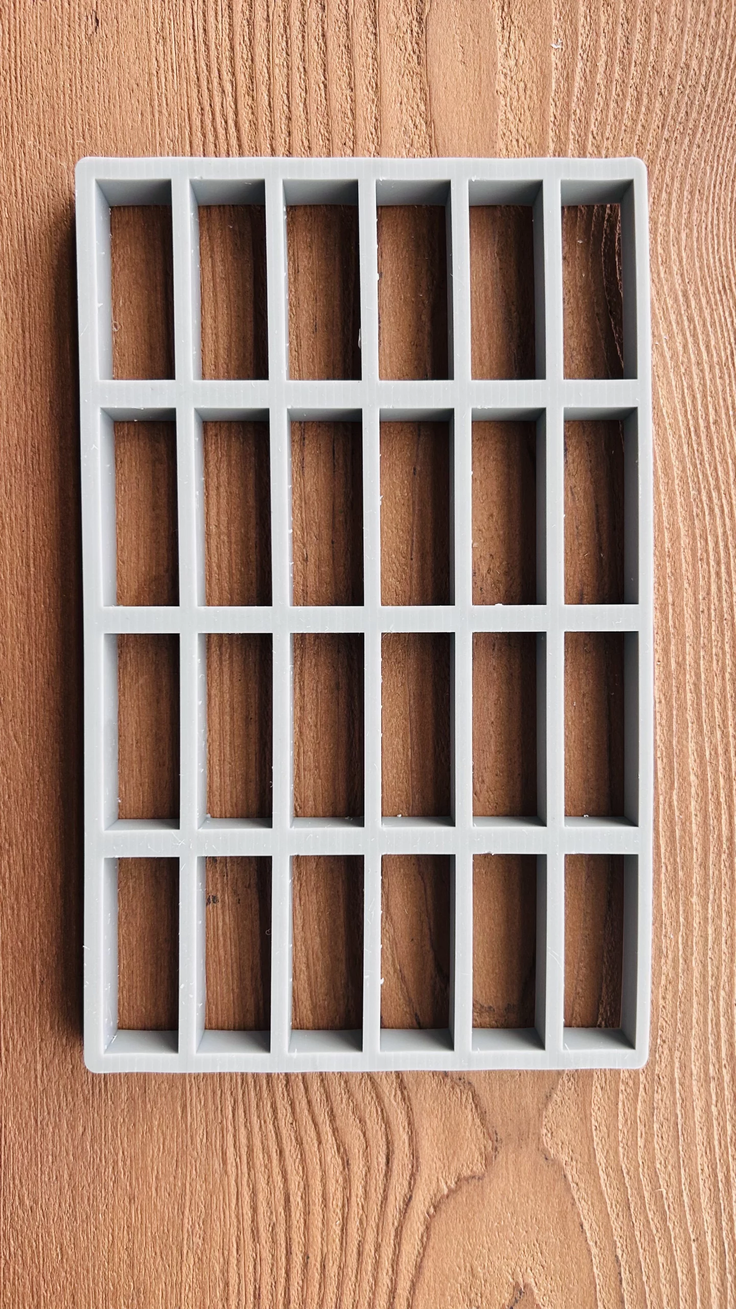
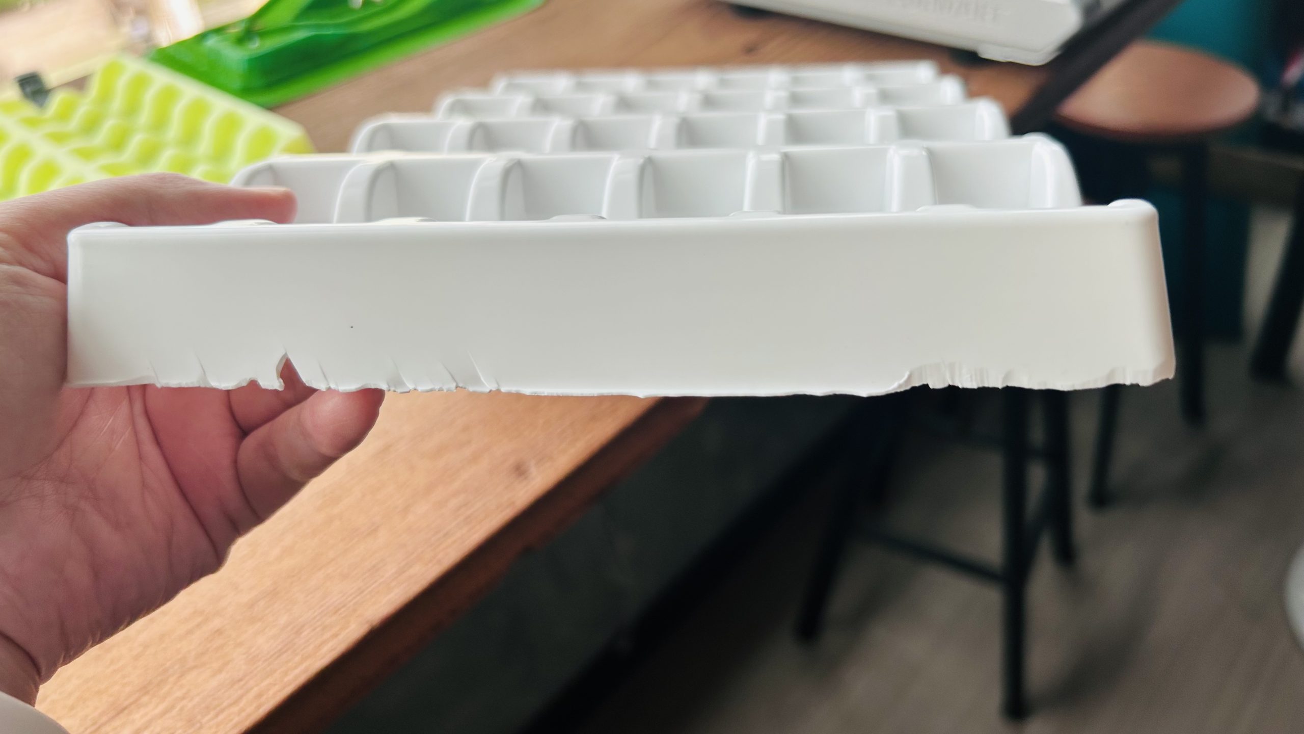
Version 2 Cutting Jig: Vacuum-Formed Mold Integration
The second jig adopted the vacuum-form mold concept, adding an external sleeve to prevent the jig from being drawn into the vacuum chamber.
Version 7 Mold: SLA Distortion Effects
The seventh mold was 3D-printed via SLA, but slight distortions caused mismatches between the forming mold and the cutting jig, affecting cut precision.
Final Solution: External Sleeve Application
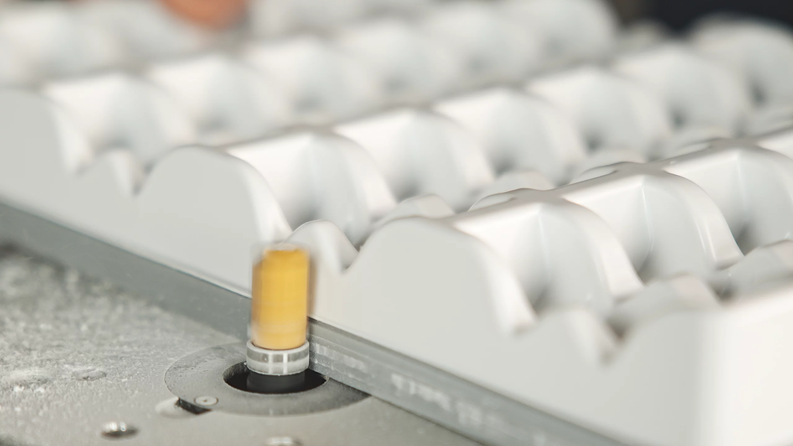
The final approach adds a matching-height sleeve around the mold’s outer ring, stabilizing the jig during vacuum forming. After forming, simply remove the sleeve to proceed with cutting—saving time and effort.

Conclusion
Through multiple design iterations and experiments, this project successfully developed a custom tray solution for Mbranfiltra.
The final design increased tray capacity and stacking stability, reduced production costs, and established an efficient mass production workflow.
Lessons learned throughout the process offer valuable guidance for future custom tray developments.
▶️Watch the full interview video
Want to rapidly produce custom trays and boost your production efficiency?
Get your
FORMART Smart Vacuum Forming Machine
today and take your design from prototype to mass production in one seamless step!
👉 Schedule a personalized consultation or request a quote
- 📧 Email: service@myyardtech.com
- 📘 Facebook: facebook.com/myyardtech
- 📸 Instagram: instagram.com/my_yard_global

No Comments